K-Net Photos

Welcome to archived photos on media.knet.ca

[ stop the slideshow ]

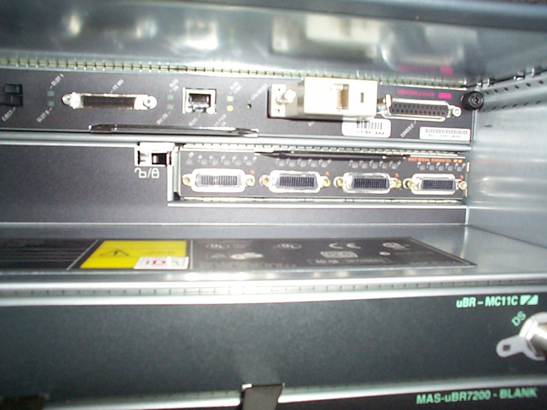
Once the port adapter card has been inserted all the way, the latch needs to be moved to the lock position.

aae.jpg The back of the linkway terminal. The panel to be removed is at the bottom left of the Linkway. It is held in place with 4 smallThumbnailsThe panel is replaced with the port adapter card. The card is inserted with the circuitboard facing down.The back of the linkway terminal. The panel to be removed is at the bottom left of the Linkway. It is held in place with 4 smallThumbnailsThe panel is replaced with the port adapter card. The card is inserted with the circuitboard facing down.The back of the linkway terminal. The panel to be removed is at the bottom left of the Linkway. It is held in place with 4 smallThumbnailsThe panel is replaced with the port adapter card. The card is inserted with the circuitboard facing down.The back of the linkway terminal. The panel to be removed is at the bottom left of the Linkway. It is held in place with 4 smallThumbnailsThe panel is replaced with the port adapter card. The card is inserted with the circuitboard facing down.The back of the linkway terminal. The panel to be removed is at the bottom left of the Linkway. It is held in place with 4 smallThumbnailsThe panel is replaced with the port adapter card. The card is inserted with the circuitboard facing down.The back of the linkway terminal. The panel to be removed is at the bottom left of the Linkway. It is held in place with 4 smallThumbnailsThe panel is replaced with the port adapter card. The card is inserted with the circuitboard facing down.

Once the port adapter card has been inserted all the way, the latch needs to be moved to the lock position.